


Overview
e-Lighting Modular 8I / 8O is a module with 8 digital inputs and 8 relay type outputs with functions to monitor the state of contacts (switches), lighting control, curtains or blinds control, delay timers to switch off outputs and pulsecount inputs for water and energy monitoring. The device can be used also to monitor the state of signals in cabinets and actuate with its outputs over contactors to switch on and off different elements of an installation. The device has dry contact digital inputs and potential free relay outputs. The device is connected to a e-Room Modular controller or to an e-Bus Modular that provide supply power and communication through the bus of the controller. Several input/output configurations are available depending on the model selected.
General features:
- Dry contact digital inputs to monitor potential free contacts.
- Inputs with shared ground every two inputs.
- Available configurations for every input: Contact type input, blinds control inputs, pulsecount input S0 type.
- Possibility to configure each input as NO or NC.
- Potential free relay outputs to control loads.
- Shared common terminal for every two output relays.
- Outputs 1 and 2 with biestable relay.
- Outputs 3 to 8 with 5 A relay.
- Available configurations for every output: Switch on/off contact, blinds control.
- Possibility to configure each output as NO or NC and save its status in the event of a power failure (persistent).
- Side connector to conect several e-Lighting to one controller (read controller instruction sheets).
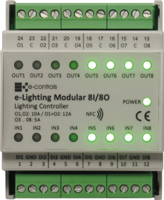
- Front panel with led indicators to signal inputs and outputs status.
Up to two e-Lighting Modular devices can be connected to an e-Room Modular controller and up to 3 e-Lighting Modular devices can be connected to an e-Bus Modular bus controller.
Through the communication bus of the e-Room Modular or the e-Bus Modular it is possible to access to modify the status of the equipment outputs and monitor their status, as well as configure the operation of each output from the equipment configuration parameters.
Installation
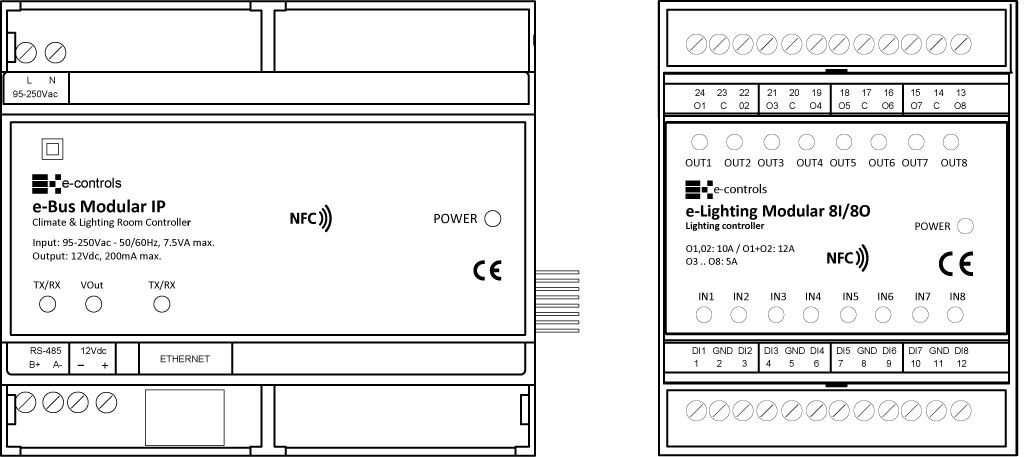
To connect e-Lighting equipment to e-Room Modular or e-Bus Modular, use a side connector supplied with the equipment:
The product is designed to be installed in a DIN EN 60715 cabinet. It must not be installed over shelves, behind curtains, over or near to heat sources or exposed to direct solar radiation.
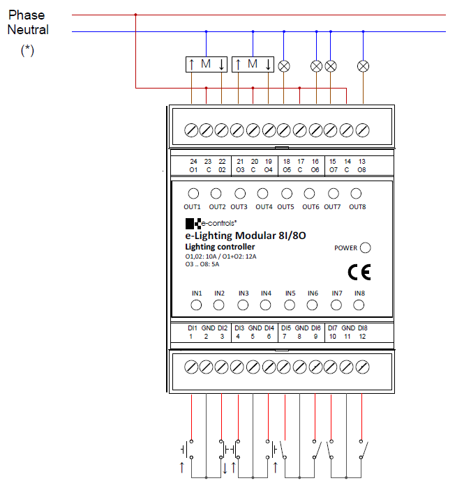
Installation drawing. Example for blind motor and for lighting control:
Important:
- For a correct operating of the system it is necessary to install the device separating the very low voltage wires (inputs, bus) from the mains wires (device supply and outputs) in the cabinet.
- Use shielded wire for the communication bus of the BMS system.
- Use the correct wires as specified in the installation drawing of the device.
Caution:
- Before installing or removing the device, make sure that there is no mains voltage present in the wiring to be connected or near the unit.
- Do not cut or roll up the wires to be connected to the device.
- Do not work on the wiring with wet hands.
- Do not open or drill through the device.
- Keep the device and the supply wires away from moisture and dust.
- Use a damp cloth to clean the device.
Installation steps:
- Disconnect the supply voltage of the cabinet.
- Insert the side connector provided, in the left handside female connector of the e-Lighting.
- If more e-Lighting devices need to be connected, remove the right side label of the device.
- Place the device on the right side of the e-Room Modular, or the e-Bus Modular or another e-Lighting device. Open the cabinet and install the device in the DIN rail placing the black clip at the bottom. Pull down the clip and press the device to insert it into the rail. Release the clip and check the device is correctly fitted.
- Verify that all the wires are installed following the constructive mounting diagram provided.
- Connect the power supply and verify the correct operating of the device.
Integration
The integration of the equipment in a control network will be carried out through the e-Room Modular or e-Bus Modular header controller. Consult the web page of the corresponding product to see the characteristics of each product.


