Overview
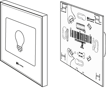
e-Touch Flexi is a complete family of touch switch products with fully customizable and configurable pushbuttons, that solve any request in lighting control, scenes management, climate control, binds, curtains or any other request for control. The touch switch is connected to an intelligent multiprotocol e-Bus Coupling frame and provides the communication protocol that best fits any project.
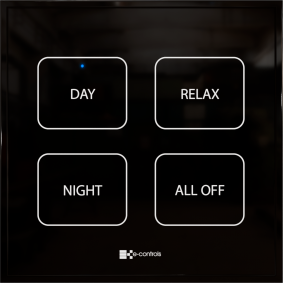
Every panel is including a unique innovative patented solution designed by E-Controls in which the pushbuttons aesthetic are designed for every project and are printed in a special paper which is later inserted in the panel, providing a fully flexible solution of the pushbuttons definition and achieving a perfect final look and feel that perfectly fits every request. Any pushbutton can be freely defined, choosing the background colour and icons or text desired for every tactile zone. Through the E-Controls webpage e-Touch Creator it is possible to design and personalize the pushbuttons of every panel, but also to ask for the quick printing service provided by the company.
A wireless NFC sensor is also present on the device and allows exchanging information with the EConfigurator APP of E-Controls, to configure the device instantly, reducing the installation programming costs drastically.
A temperature sensor is also available in the device and provides the temperature of the zone. The device is also including a proximity infrared sensor to detect nearly movements to automatically switch on the device
LEDs to easily track the device in dark conditions.
The e-Touch Flexi 2R-4P model features 4 buttons with 1 touch zone on every button and a led indicator centered on the button, which lights up when the button is pressed, providing an unmatched tactile feel.
Throughout an aesthetically innovative design, the product is finished in white or black colour (other colours available upon request), and stands out just 8,5 mm from the wall, making it one of the narrowest devices on the market and it becomes really attractive to interior designers and architects.
Commisioning of global functions of the touch switch
The touch switch is configured in two possible ways:
- Through the e-Bus Coupling frame using the communication bus selected.
- Through the E-Controls EConfigurator APP and the NFC proximity wireless data transfer technology. For this, download the APP from Play Store and install it in a mobile phone with Android operating system.
Click on this link from a mobile phone or tablet with Android operating system to download the EConfigurator APP.
General features of the device
- 4 Buttons
- 1 touch zone per button
- Total 4 touch zones
- Customizable and interchangeable touch buttons
- 4 led indicators
- NFC wireless interface
- Temperature sensor
- Proximity and brightness sensor
- Dimensions: 86x86x8,5 mm
100% customizable design
The flexible solution of customizable buttons allows you to redesign the touch switch at any time with a minimum cost, since it is posible to modify the position of the buttons or also to redesign them, replace or exchange them as many times as desired, without changing any device.

The technology designed by E-Controls allows you to manage the order of the material in a flexible way and adapted to the building construction schedule, being possible to provide the e-Touch switch devices and the e-Bus Coupling frames first, and then design the buttons later, according to the project request and supply them at any time, without the need to be at the same time than the touch switches are shipped.
Click on this link to go to the e-Touch Creator website
Adaptable to any protocol
The e-Touch system allows you to choose at any time the communication protocol that best fits any project, thanks to a connector that allows you to connect the touch switch to a bus coupling unit or intelligent frame, of which there are different models for the most used protocols in building automation.
Installation
The product must be installed with the e-Bus Coupling frame in a universal flush mouniting enclosure.

NOTE: Read the instruction sheet before installing the product.
- Disconnect the power supply of the bus coupling unit to which the touch switch will be connected.
- Assemble the plastic frame on the touch switch paying attention that the ventilation slots are in the lower and upper left side.
- Clip the touch switch e-Touch Flexi into the holes of the front connector on the bus coupling unit, and press until the frame will be firmly fixed to the wall and pressed by the keypad.
- Apply supply power to the device and check the front led indicator flashes.
- Configure the device according to the bus coupling unit selected.
- Remove the front protective film of the device.
Caution
- Disconnect the device from the power supply before mounting or moving it.
- Do not leave cables peeled or turned around the device.
- Do not connect the device with the hands wet.
- Do not open or hole the device.
- Keep the device and cables away from humidity and dust.
- Clean the front cover with a water moisture soft cloth.
Integration
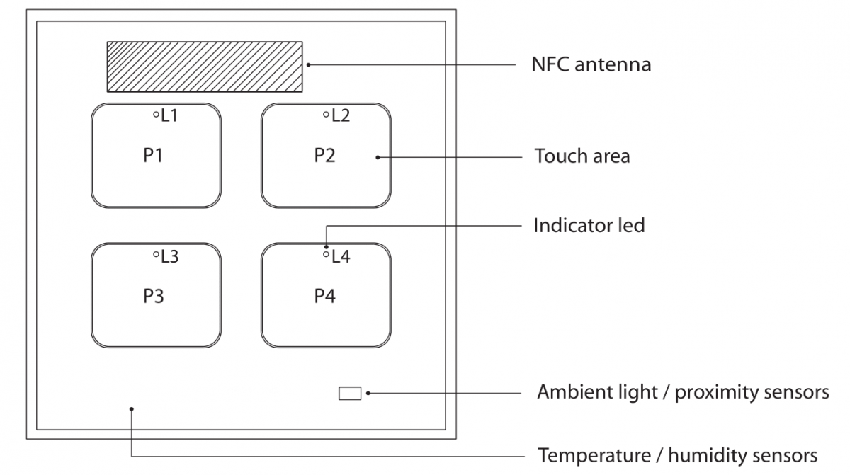
This touch switch has 4 buttons arranged in a 2x2 grid with one touch zone on each, that can be configured with the desired function. Depending on the type of bus coupling unit selected, the touch switch can do some functions or others, based on the protocol selected and the functions defined in the communications standard of every protocol.
In order to properly configure each touch zone it is necessary to know the number of each pushbutton. The following image shows the figures that define each touch zone:

If a DALI 2 bus coupling unit ref. BC.080001-001 or BC.582001-001 is selected to operate with a DALI controller, it is necessary to use manufacturer tool of the DALI controller to do the configuration of each pushbutton function. To do this, each pushbutton number will be used to assign to each instance of the DALI bus.
If a MASTER bus coupling unit is selected, like the model e-Bus Coupling DALI Master ref. BC.581002-001 or the model e-Bus Coupling 0-10V ref. BC.501001-001, it is necessary to use the APP EConfigurator tool to configure the functions of each touch zone.
Read the documentation of the selected e-Bus Coupling frame, for the integration of the device on the corresponding communication bus protocol.


 | Passatge Garrotxa, 6 | 08830 Sant Boi de Llobregat | Barcelona | Spain | Tel.: +34 93 652 55 21 | Fax +34 93 652 55 22