Overview
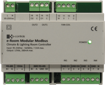
The e-Room Modular 4I/5O Modbus 12V is a low cost fan-coil controller with remote communication, designed for DIN-rail mounting. It combines climate and lighting control functions, managing the switching on and off of both systems according to the occupancy status of a room or area, through 4 inputs and 5 outputs available on the device to perform different functions.
The device is specially designed to provide maximum comfort and optimal energy efficiency for the installation, regulating the climate to reach the level desired by the user.
The unit provides different selectable configurations depending on the type of installation and required functionality. It includes a communication bus and a power output to connect a display so that the user can manage climate control. It also includes a Modbus communication bus for remote communication with a BMS system for global building management.
e-Room Modular 4E/5S Modbus 12V is a device 100% compatible with the old model e-Room Controller 4E/5S Modbus 12V.
Main Features Summary
- Fan-coil controller for 2-pipe and 4-pipe installations.
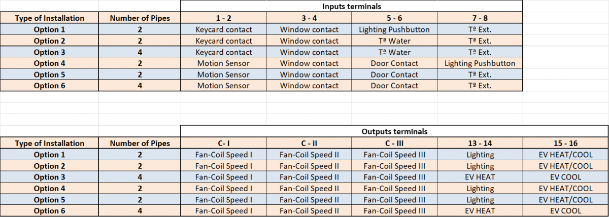
- Six possible configurations according to the type of installation.
- Two self-configurable dry-contact inputs: keycard/motion detector, window contact
- Two self-configurable analog inputs: water probe for mode change/door contact/lighting pushbutton, external temperature/lighting pushbutton.
- Three relay outputs for fan-coil speed.
- Two relay outputs for valves (2/4 pipes) + room/courtesy lighting.
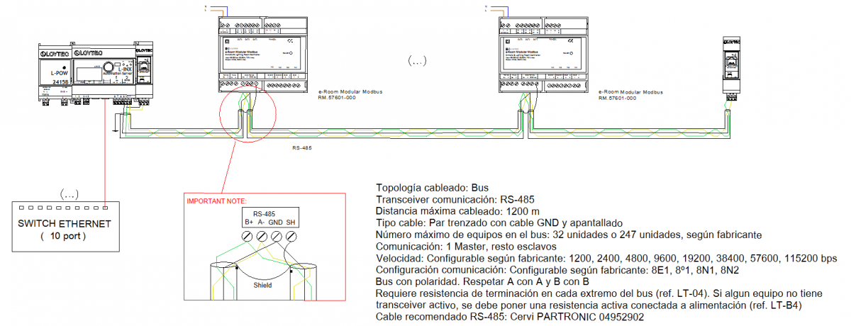
- Modbus RTU communication protocol with RS-485 interface for remote management through BMS.
- RS-485 interface communication bus for connection with the sensor-display.
- Power supply from the mains.
- Configurable economy mode when the room is unoccupied (off/setpoint change).
- Configurable actual and user setpoints for cooling and heating.
- Automatic start-up in case of temperature excess or frost risk.
- Fan-coil type configuration: 3-speed / 1-speed.
- Configurable fan-coil locked speed when there is no demand.
- Configurable cooling/heating setpoint in ECO mode.
- Configurable dead band between cooling and heating.
- Delay to switch to stand-by when the room becomes unoccupied.
This table summarizes the pre-programmed operating modes and the function of each input and output of the device for every mode.
Refer to the document “Configuration Manual” of the device, which describes the configuration parameters and the procedure to modify the predefined parameter values.
Installation
The device is designed for installation in cabinets with standard EN 50 022 DIN rail mounting. It must not be installed on shelves, behind curtains, near or above heat sources, or exposed to direct sunlight.
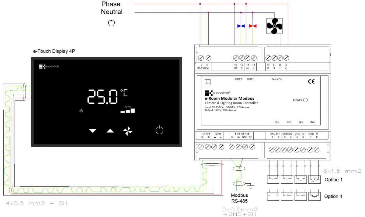
Installation drawing for 2 pipes systems:
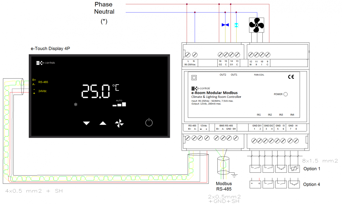
Installation drawing for 4 pipes systems:
Important:
- Install the device inside the electrical panel, keeping extra-low voltage signal wiring (inputs) separated from low voltage wiring (outputs).
- Use shielded cable for the communication channel with the BMS.
- Always follow the wiring type indicated in the installation diagram.
Precautions:
- Before installing, removing, or cleaning the device, ensure that no mains voltage is present on the cables or near the device.
- Do not cut, splice, or coil the mains cables connected to the device.
- Do not handle connections with wet hands.
- Do not open, drill, or modify the product.
- Keep the device and cables away from moisture and dust.
- Clean only with a slightly damp cloth using water.
Mounting Steps:
- Disconnect the power supply of the electrical panel.
- Insert the device onto the DIN rail with the black latch positioned at the bottom; pull the latch downward, press the device until it clicks into place, and release the latch to secure it.
- Verify that the panel wiring follows the installation layout diagram.
- Connect the cables to the terminals according to the wiring diagram and attach them to the device.
- Restore power supply and check proper operation.
- Close the electrical panel.
Integration
The device includes an RS-485 communication interface that operates using the Modbus RTU standard protocol. Through this interface, it is possible to access all configuration parameters of the device, monitor various operating variables such as room temperature, occupancy status, or fan-coil speed, and remotely control the unit to activate it, change the temperature setpoint, or modify any other available parameter.
The device provides multiple configuration parameters that allow the product to be adjusted to the specific needs of each installation type. All these parameters can be configured through a simple configuration menu accessible from the device’s front keypad and display, or remotely via the communication bus.