


Overview
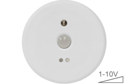
e-Multisensor AutoDim 1-10V is an innovative stand-alone multisensor with a motion and lighting sensor to perform a digital control to adjust an installation light level to a constant value, to get the goal of optimized energy installation consumption.
The device has a high accurate motion sensor to detect motion and switch on lights when the zone becomes occupied. When the lights are on, the device measures at any time light level and reaches the preset intensity light value, guaranteeing an optimal light level and minimizing the energy consumption. In order to be able to fully optimize energy saving functions, the device automatically switches off lights after a preset time that starts counting from the last valid detection.
A new feature is available in devices manufactured from 2017 to configure the minimum light level intensity, to make it operate with any luminary manufacturer. Some LED luminaries switch off the light when a minimum light level is desired, some other ones keep light switched on and some others make it blink at minimum light level. To avoid this situation, the new feature can be used to adjust the minimum light level desired.
Resume of general features:
- Motion detector with infrared PIR sensor
- Detection area 6m diameter installed at 2,5m from floor
- Installable up to 8m from floor
- Light sensor to measure the light level in the zone
- Constant light level in the same device for automatic light dimming
- 10A relay for on/off light switching
- Output 1-10V with current source up to 10mA
- Minimum light level configurable by the installer
- 5 sec to 30 min timer for automatic light switching off
- Potentiometer to adjust detection sensitivity to let install device at any place
- External input to create a light scene
- Configurable light level in scene mode
- External input for manual light dimming
- LED indicator of motion detection
- Pushbutton for device configuration
- Installable in Surface enclosure
- Supply input 95 to 250Vac 50/60Hz
Motion sensor
The motion sensor has a detection area defined on the device detection diagram section. The sensor length depends on the installation height and detection sensibility could be modified throughout a potentiometer which allows to adjust it to each kind of environment and avoids performing false detections.
In stand-by, the relay output contact will be open and power won’t be present on the output terminals L’-N, for that reason the lights will be off. Relay output will switch on when motion will be detected and at the same time lights will switch on to their maximum value. After a preset time from last valid detection, the relay output will switch off automatically. This switch off time could be predefined throughout a potentiometer.
When power supply is applied on the device, motion sensor requires a stabilization time while the device is in a non-detection state (refer to Technical features).
Light sensor
Light sensor is measuring constantly the light level inside the defined area of the radiation diagram of the sensor. When the relay output is switched on, lights will switch on to their maximum value and device will start to perform the automatic constant light control until the lights will reach the pre-configured light level Front pushbutton of the device is used to configure zone’s lighting set point. Refer to Device configuration section to adjust the lighting set point.
Auxiliary input
The device has an auxiliary phase commutation digital input (refer to installation diagram) which could be configured as a Scene mode (in switch mode) or dimmer (in pushbuttonmode).
Scene function (switch mode), is used for example in meeting rooms to reduce light level when the user wants to show a projection, or to fix a light level on the hospital corridors during nights. When input sets to scene mode (switch mode), the input activation disables sensors functionality and modifies the light level to a preset constant level. Light value could be set as required (Refer to Device Configuration). The input deactivation, enables again sensor functionality and lights will go back to preset set point.
Dimmer function (pushbutton mode) allows user to temporarily modify a zone light value manually, increasing or reducing light level as required. When input is configured on dimmer mode (pushbutton mode), by pushing it the light level increases until the pushbutton is released. Light level preset will be constantly maintained at any time in the zone, until lights will switch off because of no motion detected. When lights will switch on again, light level will reach again the preset value configured during the installation phase.
Installation
The device has an enclosure for flush mounting in roof ceilings. If a surface mounting is needed, the surface mounting enclosure ref AC.000001-000 must be used.
Mounting instructions
- Drill a 65mm diameter hole on the ceiling.
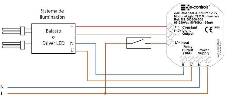
- Connect wires on the correct terminals:
• Connect the power supply in the L and N terminals.
• Connect the L’ and N relay output to the luminary terminals.
• Connect the +/- terminals of the 1-10V output to the +/- terminals of the ballast or driver, respecting the polarity.
• Optionally connect the auxiliary input to a pushbutton or switch depending on the installation requests.
- Adjust the potentiometer of the relay switch on time placed on the side of the device, to the desired value.
- Adjust sensibility detection potentiometer on the side of the device, to the desired value.
- Clip the springs and insert the product into the hole, releasing the springs when placed in (see figure).
- Power up the supply voltage. Check the relay output by short pressing the front Pushbutton.
- Configure light set-point depending on desired level.
Caution
- The device can’t be installed over shelves, behind curtains, near heat/cool air handling units and avoid direct sun radiation over the device.
- Disconnect the device from the power supply before mounting or moving the sensor.
- Do not leave cables peeled or turned around the device.
- Do not connect the device with the hands wet.
- Do not open or hole the device.
- Keep the device and cables away from humidity and dust.
- Clean the front cover with a water moisture soft cloth.


