


Overview
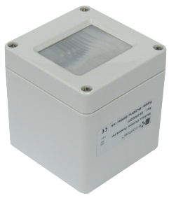
Multilux 180 DALI is an innovative multisensor designed to be installed in large areas like industrial buildings, freezing areas, airports, outdoor lighting, etc., providing a lighting control based on motion detection and lighting dimming, giving a high energy saving switching lights off in unoccupied zones and dimming lights depending on the setpoint configured.
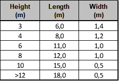
A very accurate motion sensor allows installing the device up to 18 metres high, being an ideal product for logistic areas and other buildings where would be able to switch lights on and off when people is detected. The device is including an special lens for optimal detection in corridors, because of a thin coverage area in its base and a wide detection area along the corridor.
An integrated lighting sensor on the device with a detection range of 0 to 500 lux (in the sensor lens) and with a resolution of 12 bits, measures the light level on the zone and adjusts it depending on the daylight level inside the building and the setpoint configured.
Three product references are available: DALI, TP/FT-10 LonWorks twisted pair and PowerLine LonWorks to communicate through electrical mains. The DALI model has been designed to operate in a DALI network with a DALI gateway like anyone of the LDALI family products. The LonWorks models include all the functions for an automatically lighting control.
The device can operate from -20ºC to +50ºC and is mounted in an IP65 surface mounting enclosure, designed to be installed in hostile environments like freezing warehouses and outdoor lighting.
The following table sumarizes the detection area of the device depending on the installation height:
Introduction
The control system to install with this product must be based at least with three elements: This multisensory, a DALI gateway compliant with the DALI V2 standard and a set of DALI luminaries over which the lighting control through the DALI bus will be done.
Operating
The device is constantly measuring any motion detection in the area of operation, providing instantly any change as a detection event to the DALI network. The light level is also measured and remains as a value in the device for a polling query from the DALI gateway. With this information, the DALI gateway is responsible for the lighting control over the lighting groups defined previously in the lighting project.
LED indicator
A red LED indicator in the multisensor blinks when a valid detection is detected by the device. This LED can be seen through the semi-transparent lens in front of the device.
Detection sensibility
The device is including a potentiometer to adjust the motion detection sensibility. Turn the potentiometer clockwise to adjust more sensibility and vice versa.
To adjust the sensibility the device must be connected to the bus and powered.
Enable/disable LED indication
Through the configuration pushbutton of the device it is possible to enable and disable the LED indicator, to avoid the blinking when motion is detected.
Press the configuration pushbutton of the device during 3 seconds to enable/disable the LED indication operation.
Installation
Requirements for the product installation
- The installation of the device requires a crosshead screwdriver, a flat 3mm screwdriver and an stripping tool.
- Use a two wire 1,5mm2 section with jacket to ensure optimal IP waterproof. Unfold 20 mm of the jacket and peel the cable 5mm to contect it to the device.
Installation process
The enclosure of the device must be installed in a flat surface.
- Be sure that there is no DALI voltage in the DALI wire to connect to the device.
- Unscrew the four screws of the multisensor cover.
- Feed the cable through the fitting conduit and connect the wires into the terminals. The DALI bus does not have polarity.
- Fix the device and screw the fitting conduit nut. Be sure that the jacket has been correctly fastened, otherwise the waterproof can’t be guaranteed.
- Make two holes on the ceiling and fix the device firmly.
- Close the device with the cover in correct position and fix it with the four screws.
- Ensure that the cover is closed, otherwise the waterproof can’t be guaranteed.
- Power the device with the DALI supply and check the red LED indicator is ON for around 60 seconds.
- Configure the device with a DALI tool.
Caution
- The device can’t be installed over shelves, behind curtains, near heat/cool air handling units and avoid direct sun radiation over the device.
- Disconnect the device from the power supply before mounting or moving the sensor.
- Do not leave cables peeled or turned around the device.
- Do not connect the device with the hands wet.
- Do not open or hole the device.
- Keep the device and cables away from humidity and dust.
- Clean the front cover with a water moisture soft cloth.
Integration
The device has been designed to operate ina DALI control network as an slave device. To operate in the network, a DALI gateway including all the functions to scan and comssion devices is required. The product family LDALI provides all the required functions to manage the Multilux multisensors.


