Overview
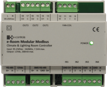
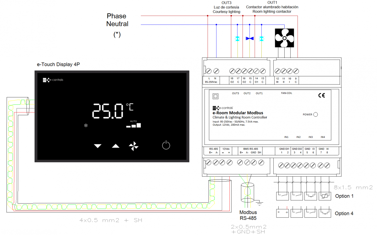
The e-Room Modular 4I/6O Modbus 12V is a low cost fan-coil controller with remote communication, designed for DIN-rail mounting. It combines climate and lighting control functions, managing the switching on and off of both systems according to the occupancy status of a room or area, through 4 inputs and 5 outputs available on the device to perform different functions. This model allows a dual lighting control when configured to operate in 2-pipe installations. In this configuration, output OUT1 is used to control the main lighting contactor in a hotel room, and output OUT3 is used to control the courtesy lighting at the room entrance.
The device is specially designed to provide maximum comfort and optimal energy efficiency for the installation, regulating the climate to reach the level desired by the user.
The unit provides different selectable configurations depending on the type of installation and required functionality. It includes a communication bus and a power output to connect a display so that the user can manage climate control. It also includes a Modbus communication bus for remote communication with a BMS system for global building management.
e-Room Modular 4E/6S Modbus 12V is a device 100% compatible with the old model e-Room Controller 4E/6S Modbus 12V.
Main Features Summary
- Fan-coil controller for 2-pipe and 4-pipe installations.
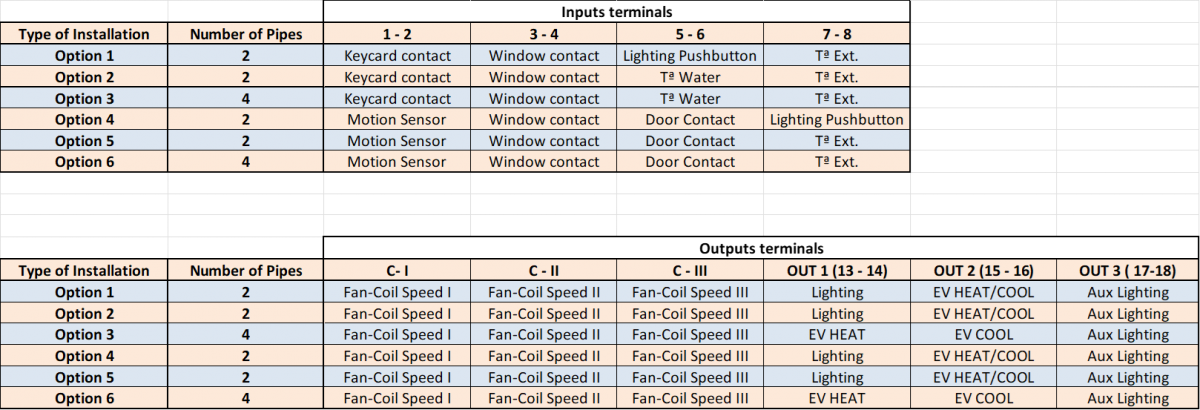
- Six possible configurations according to the type of installation.
- Two self-configurable dry-contact inputs: keycard/motion detector, window contact
- Two self-configurable analog inputs: water probe for mode change/door contact/lighting pushbutton, external temperature/lighting pushbutton.
- Three relay outputs for fan-coil speed.
- Two relay outputs for valves (2/4 pipes) + room/courtesy lighting.
- One relay output for courtesy lighting control in hotel rooms.
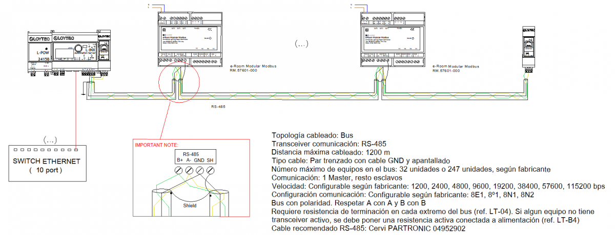
- Modbus RTU communication protocol with RS-485 interface for remote management through BMS.
- RS-485 interface communication bus for connection with the sensor-display.
- Power supply from the mains.
- Configurable economy mode when the room is unoccupied (off/setpoint change).
- Configurable actual and user setpoints for cooling and heating.
- Automatic start-up in case of temperature excess or frost risk.
- Fan-coil type configuration: 3-speed / 1-speed.
- Configurable fan-coil locked speed when there is no demand.
- Configurable cooling/heating setpoint in ECO mode.
- Configurable dead band between cooling and heating.
- Delay to switch to stand-by when the room becomes unoccupied.
This table summarizes the pre-programmed operating modes and the function of each input and output of the device for every mode.
Refer to the document “Configuration Manual” of the device, which describes the configuration parameters and the procedure to modify the predefined parameter values.
Installation
The device is designed for installation in cabinets with standard EN 50 022 DIN rail mounting. It must not be installed on shelves, behind curtains, near or above heat sources, or exposed to direct sunlight.
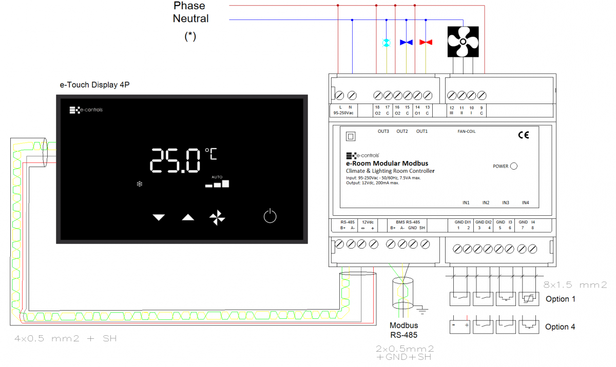
Installation drawing for 2 pipes systems:
Installation drawing for 4 pipes systems:
Importante:
- Instalar el equipo en el cuadro eléctrico separando el cableado de señales de muy baja tensión (entradas) del cableado de baja tensión (salidas).
- Utilizar cable apantallado para el canal de comunicaciones con el BMS.
- Seguir siempre el tipo de cableado indicado en el esquema de instalación.
Precauciones:
- Antes de instalar, desinstalar o limpiar el equipo, asegúrese de que no haya tensión en los cables de red ni cerca del equipo.
- No cortar, empalmar ni enrollar los cables de red conectados al equipo.
- No manipular conexiones con las manos mojadas.
- No abrir, perforar ni modificar el producto.
- Mantener el equipo y los cables alejados de la humedad y el polvo.
- Limpiar únicamente con un paño ligeramente humedecido en agua.
Pasos de montaje:
- Desconectar la alimentación del cuadro eléctrico.
- Insertar el equipo en el carril DIN situando el gatillo negro en la parte inferior; tirar del gatillo hacia abajo, presionar el equipo hasta encajarlo y soltar el gatillo para fijarlo.
- Verificar que el cableado del cuadro sigue el esquema constructivo de montaje.
- Conectar los cables en los terminales según el esquema y acoplarlos al equipo.
- Restablecer la alimentación y comprobar el funcionamiento.
- Cerrar el cuadro eléctrico.
Integration
The device includes an RS-485 communication interface that operates using the Modbus RTU standard protocol. Through this interface, it is possible to access all configuration parameters of the device, monitor various operating variables such as room temperature, occupancy status, or fan-coil speed, and remotely control the unit to activate it, change the temperature setpoint, or modify any other available parameter.
The device provides multiple configuration parameters that allow the product to be adjusted to the specific needs of each installation type. All these parameters can be configured through a simple configuration menu accessible from the device’s front keypad and display, or remotely via the communication bus.