Overview
e-Bus Coupling is a family of multiprotocol intelligent coupling units that are connected to the e-Touch Flexi touch panels, to provide a communication protocol or also different inputs and outputs to perform a control solution over a lighting system, management of scenes, blinds or curtains automation or any other control required in the installation.
Different models of coupling units e-Bus Coupling device are available: some models with communication protocol to integrate into a BMS control system, and some others with physical inputs and outputs to manage a control system.
The e-Bus Coupling KNX is a communication interface or frame that facilitates the connection of any e-Touch Flexi or e-Touch Panel touch switch to the KNX communications bus. Each touch switch has its own layout of buttons and LEDs (for further information see the instructions sheet of each touch switch). The buttons are grouped into paired buttons and individual buttons. Paired buttons can be configured to become individual buttons. Both paired buttons and individual buttons can perform multiple functions, all of which are configurable with the ETS software.
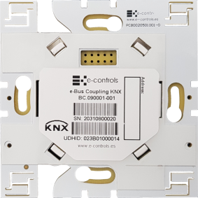
e-Bus Coupling KNX has an standard format that can be installed in a universal 66x66 mm wall mount enclosure and includes some holes at 60x60 mm to fix into standard enclosure. The following image shows the device from the back side:
The device automatically recognizes the touch switch inserted in the device. Use the corresponding stencil in the ETS tool to configure the touch switch accordingly.
Programming LED The unit has a LED on the rear marked “PROG”, which indicates whether the unit is in programming mode. When the unit is connected to the power supply or reset, the programming LED flashes.
Programming push-button The unit has a push-button on the rear marked “PROG” to activate/deactivate the unit’s programming mode.
Installation
Installation drawing of the product

Product assembly
The device is installed in a universal flush mounting enclosure or also in a plasterboard enclosure, plus any touch switch of the e-Touch Flexi or e-Touch Panel family products.
Read carefully the installation steps of the device explained in the instruction sheet.
Importante:
- For the e-Bus Coupling KNX frame to work, an e-Touch Flexi or e-Touch Panel touch switch must be connected to the unit.
- Follow the KNX standard instructions for the installation of the wiring in the building.
Unit mounting steps:
- Disconnect the power supply from the KNX bus to which the frame is to be connected.
- Connect the KNX bus to the marked unit.
- Attach the unit to junction box with two screws. To connect an e-Touch Panel touch switch, screw in the extender that comes with the touch switch, inserting the two upper slots of the extender into the frame so that the touch switch can be attached on all four sides.
- Mount the plastic frame on the touch switch, making sure that the air slots are at the bottom and top left of the touch switch.
- Insert the e-Touch Flexi or e-Touch Panel touch switch into the openings of the front connector of the frame until the white clips of the switch line up with the slots of the frame and apply pressure until the frame touches the wall and is held in place by the touch switch.
- Connect the power supply to the KNX bus and verify that one of the blue LEDs on the front of the touch switch lights up within the first 25 seconds.
- Configure the unit in accordance with the steps indicated in the “Configuration” section.
Caution:
- Disconnect the device from the power supply before mounting or moving the unit.
- Do not leave stripped wires or rolled-up wires near the unit.
- Do not connect the device with wet hands.
- Do not open or pierce the product.
- Keep the device and the wires away from humidity and dust.
- Clean the front of the device with a slightly damp cloth.
Integration
Configuration of the unit in the KNX bus Once the unit has been installed, it can be configured with the application available for the ETS programming tool. The ETS version to load the application of the unit must be at least 5.0. It is essential to choose the same touch switch that is installed in the options; if the other touch switch is chosen, it will not work and the LEDs will enter the activation sequence that indicates wrong touch switch.


 | Passatge Garrotxa, 6 | 08830 Sant Boi de Llobregat | Barcelona | Spain | Tel.: +34 93 652 55 21 | Fax +34 93 652 55 22